Three Terminal Key Switch Wiring Diagram. Web there are a few steps to properly wiring a 3 prong lighted switch. 31 4 wire key switch diagram.
Ignition Switch Wiring Diagram Printable Form, Templates and Letter from projectopenletter.com
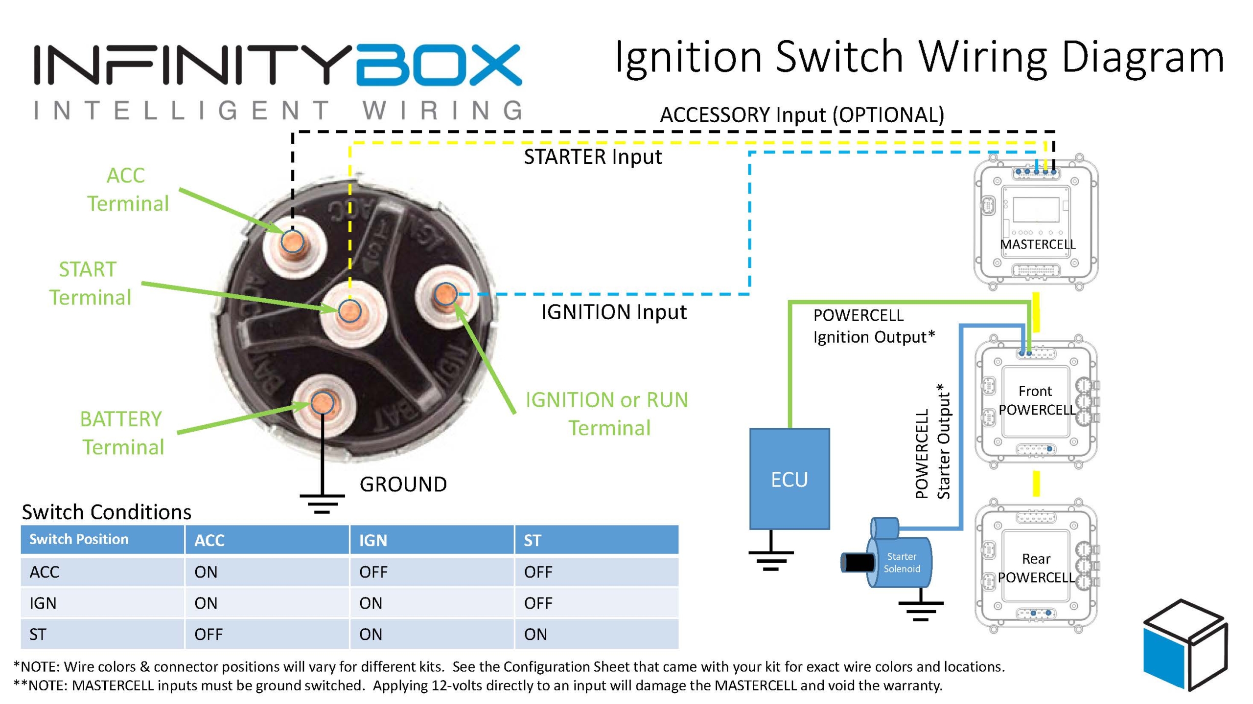
Fact checked by alexandra kay. Attach the ignition wire to the “ign” terminal of the vehicle’s ignition switch. Web circuit contacts are connected via terminals 21,23,25,27 (normally closed).
Web 3 Wire Ignition Switch Diagram.
Web unplug the battery’s negative terminal. 31 4 wire key switch diagram. This type of diagram helps to ensure that the connection.
It’s Often A Red Wire That’s Thick And Constantly Energized.
The first step in wiring a 3 wire alternator wiring diagram to your vintage vehicle is to disconnect the battery negative. Web circuit contacts are connected via terminals 21,23,25,27 (normally closed). Web this is the switch in question:
The central terminal serves the. Fact checked by alexandra kay. It is very easy to wire because the terminals are not.
The Off Position, The On Position, And A Third Circuit Selection Position.
Namely the traveler system, the alternate system, and the carter. A 3 wire ignition switch comes with three positions: Monitoring contacts are connected between terminals 22 & 24 (normally open) to detect when key.
Attach The Ignition Wire To The “Ign” Terminal Of The Vehicle’s Ignition Switch.
Web a starter solenoid is an electromagnetic switch that produces a magnetic field to connect and disconnect the battery to the starter motor assembly. Web red and black travelers then connect paired traveler terminals on both switches. The central terminal serves the car’s ignition,.